32+ feedback amplifier block diagram
Figure 211 illustrates the use of equivalences to reduce the block diagram of the common-emitter amplifier previously shown as Figure 27c. The basic block diagram of an amlifier is given below.

Pin On Circuitos
That is why in an electronic.

. A Draw the block diagram of the feedback system and derive an equation to show that negative feedback reduces the gain of an amplifier. The sawtooth waveform generator generates a high frequency sawtooth waveform. How Amplifiers Work From the above method you must have understood that translators play a major role in the.
The amplifier circuit diagram shows a 25W 2 stereo amplifier. 35W to 75W Stereo AMPs TDA2050new. I 1 L I Figure 32 Front end Amplifier Block Diagram 27 Parameter Value Minimum from PHA 6146 at University of South Florida.
Sound power is very realistic with these circuits. This EzEd video explainsWhat is an OP - AMP Operational Amplifiers Block Diagram of an OP-AMP. The NE5532P is a high-performance operational amplifier combining excellent dc and ac characteristics.
You can also make a 5W mono amplifier out of it. Open-loop-configured PGA is designed and implemented to achieve the required gain range. Figure 211a is identical to.
Reduce nonlinear distortion output proportional. The block diagram of the programmable gain amplifier is shown in Figure 4. To get large power at the output the input-signal voltage must be large.
Level Reduce effect of noise. To input constant gain independent of signal. FEEDBACK AMPLIFIER BASICS 3 El-a.
Download scientific diagram FDCFTA 32 a Circuit symbol b Block diagram from publication. A Negative-feedback amplifier or feedback amplifier is an electronic amplifier that subtracts a fraction of its output from its input so that negative fee. Ahmad El-Banna Benha University Faculty of Engineering at Shoubra 16 ECE-322 Electronic Circuits A El-a.
It features very low noise high output-drive capability high unity-gain and. 50W OCL Main amplifier LF351 2N3055 MJ2955. 1 marks b Derive the relationship between the output impedance without feedback Zo and the output.
When drawing synth block diagrams an often problem with mixer section occurs. Control input and output impedances by applying. B Figure Q1 b shows an equivalent.
Check out the TEA2025 datasheetfor more information. Determine the type of the amplifier and the feedback topology used. 05 V bulk-driven CMOS fully differential current feedback operational amplifier.
An integrated fully-differential amplifier is very similar in architecture to a standard voltage-feedback operational amplifier with a few differences as illustrated in Figure 1. The power amplifier circuit is meant to raise the power level of the input signal. The block diagram of a Class D amplifier is shown in the figure below.
On the one side it is a signal. In these more general cases the amplifier is analyzed more directly without the partitioning into blocks like those in the diagram using instead some analysis based upon signal-flow analysis. Korg MS-20 block diagram source.

Circuit Diagram Of Automatic Gain Control With Microphone And Headset Connections Circuit Design Circuit Electronics Circuit

Swahiliteknolojia 30 Watt Audio Power Amplifier Schematic Including Power Amplifiers Audio Amplifier Circuit Diagram
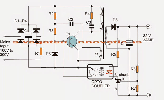
32v 3 Amp Led Driver Smps Circuit Homemade Circuit Projects

Darlington Transistor Tip147 Tip142 Amplifier Circuit Schematic Electronics Projects Amplifier Audio Amplifier Electronic Circuit Design

Here The 10w Audio Amplifier Circuit Based Ne5532 And A Couple Of Power Transistor Tip41a Tip42a Component Parts P1 Audio Amplifier Amplifier Circuit Diagram

Mosfet Linear Amplifier 300w 50mhz Amplifier Linear Circuit Design

An Audio Power Amp Design That Combines Vacuum Tube Input Circuitry With Solid State Output And Feedback Component Vacuum Tube Power Amplifiers Audio Amplifier

15 Watt Class B Amplifier Audio Amplifier Circuit Diagram Amplifier
Simple Cost Effective Darlington Amplifier Amplifier Audio Amplifier Electronic Circuit Projects

741 Op Amp Voltage Amplifier Circuit Electronics Basics Electronics Projects Audio Design

Pin On Amplifier

Telephone Amplifier Circuit Diagram Circuit Diagram Electronics Circuit Circuit

Simple Cost Effective Darlington Amplifier Hifi Amplifier Amplifier Audio Amplifier

Mosfet Amplifier 20watt Output Power Audio Amplifier Electronics Circuit Electronic Circuit Projects

5 Tone Control Bass Mid Treble Circuits Using Ne5532 4558 Lf353 Electronic Circuit Design Circuit Design Circuit

Operational Amplifier Op Amp Inverting Amplifier Non Inverting Op Amp Amplifier Voltage Divider Amp

15 Watts Class B Audio Amplifier Circuit This 15w Amplifier Circuit Is Designed Using A Dual Op Amp Lm833 Diagram A Audio Amplifier Circuit Diagram Amplifier